
Introduction
Do you know which defaults from the ASME Y14.5 standard apply to your drawings? To correctly read a drawing, you must be able to recognize the defaults from Y14.5 and understand where they apply. Recognizing defaults is a bit tricky because they do not appear on a drawing. The Y14.5 defaults are described in the standard. If you are not aware of or cannot interpret the defaults, you are missing critical information about the requirements of the drawing. This article highlights ten of the common defaults from the Y14.5 standard.
A "default" is something that applies automatically. In Windows software, defaults can be the program that opens an image file or the fonts that are automatically used when you open your word processor. One nice thing about defaults is that you can change them.
What is a default condition in the ASME Y14.5-2009 Standard?
In the Y14.5 standard, there is not a definition for defaults. I will start by defining the term "default condition" based on my interpretation of the standard and the way I use them in this article.
A default condition is a requirement, rule, specification, or method that has options allowed and one of the options automatically applies to a drawing. Default conditions can be overridden by specifying a different requirement, rule, specification, or method on the drawing.
There are two types of default conditions in Y14.5:
- Default conditions that are described in the standard and automatically apply on a drawing.
- Default conditions that impact the interpretation of a specification on a drawing.
A default condition is often indicated in the Y14.5 standard by using the words "Unless Otherwise Specified..." (followed by or preceded by a description of the default.) However, in the Y14.5 standard, default conditions are not always stated using those words. Sometimes defaults are explained using other words or terms. In Y14.5 there are also some defaults that apply to a drawing when a specification is shown on the drawing that could be interpreted multiple ways, but one way applies automatically. These various methods used make some of the defaults in the standard difficult to recognize.
One common example of a default condition from Y14.5 is Rule #1 (perfect form at MMC from paragraph 2.7). Rule #1 is a requirement that applies automatically to feature of size dimensions. There are several ways to override Rule #1. Therefore, I consider Rule#1 a default condition. A default condition may have methods to override it listed in the standard or the methods to override a default may be open to the user to specify.
How many Y14.5 default conditions can you find on the bracket drawing?
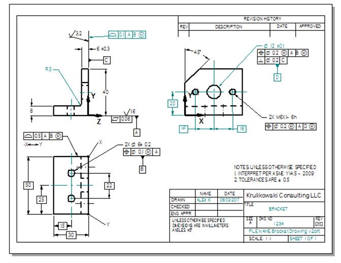
The bracket drawing is a simple part. Review the bracket drawing above and see how many default conditions you can find. You probably found several default conditions fairly quickly. But, without recognizing all of the Y14.5 defaults that impact this drawing, you will likely misinterpret the drawing. The misinterpretation could result in costly mistakes. I will highlight each of the Y14.5 defaults that apply to this drawing in the following paragraphs.
#1 The coordinate system default

This section explains what I call the "coordinate system default". This default is from paragraph 1.4(p) in the Y14.5 standard. It states, "Where a coordinate system is shown in the drawing, it shall be right handed unless otherwise specified." A right-handed coordinate system is by far the most common on engineering drawings. Therefore, it is the default in Y14.5. For example, see the balloons labeled #1 in the bracket drawing. This default applies two places on the bracket drawing.
If you want to override right-hand coordinate system default and show a left-handed coordinate system, it must be designated in the drawing. The Y14.5 and Y14.41 standards do not show an example of a left-handed coordinate system.
Without the coordinate system default, coordinate systems on a drawing could be misinterpreted. This could result in parts being made that do not fit in the assembly and tooling could be built that may need to be scrapped.
#2 The measurement temperature default

This section explains what I call the "measurement temperature default". This default is from paragraph 1.4(l) in Y14.5. It states, "Unless otherwise specified, all dimensions and tolerances are applicable at 20° C(68°F)". An example of measurement temperature default does not appear on a drawing. On the bracket drawing, the balloon labeled #2 highlights the note that invokes the standard which in turn invokes the measurement temperature default.
You can override the measurement temperature default by adding a general note to the drawing stating the temperature to be used for measurement.
The measurement temperature default is important because parts expand or contract based on their temperature. To be able to compare measurements taken in different locations, the measurement must be taken at a consistent temperature. The temperature at which a measurement is taken can impact part acceptance or function.
#3 The dimension/tolerance extent default

This section explains what I call the "dimension/tolerance extent default". This default is from paragraph 1.4(n). It states, "Unless otherwise specified, all dimensions and tolerances apply for full depth, length, and width of the feature". On the bracket drawing, several examples of where this default applies are shown with the balloons labeled #3.
The dimension/tolerance extent default can be overridden with a note stating the extent of a dimension, using a between symbol, or a limited area designation.
Without dimension/tolerance extent default, confusion could exist on the extents of a dimension. This could cause disputes over part acceptance or functional problems.
#4 The size envelope default

This section explains what I call the "size envelope default." This default is from paragraph 2.7. It states, "Unless otherwise specified, the limits of size of a feature prescribe the extent within which variations of geometric form, as well as size are allowed". On the bracket drawing, there are five examples of where this default applies. They are shown with the balloons labeled #4.
The Y14.5 standard shows several ways the size envelope (Rule #1) default can be overridden. Rule #1 can be overridden by indicating...
- The independency symbol next to a size dimension.
- A flatness symbol to apply to a planar feature of size dimension.
- A straightness symbol to apply to a diametric size dimension.
- A note overriding Rule #1 on the drawing.
- A free state note to the drawing.
- The free state symbol to apply to a size dimension.
- The note "AVG DIA" next to a diametral size dimension.
The size envelope (Rule #1) default is important because it creates an envelope boundary that ensures parts will assemble. Without Rule #!, the form deviation of a feature of size could impact its overall size boundary and create an interference condition with the mating part.
#5 The material condition default. (Rule #2)

This section explains what I call the "material condition default." This default is from paragraph 2.8. It states "Rule #2- RFS applies to the individual tolerance, and RMB applies, with respect to the individual datum feature reference, where no modifying symbol is specified". On the bracket drawing, there is one example where condition default applies; it is labeled with balloon #5.
The Y14.5 standard shows several ways the material condition (Rule #2) default can be overridden. They are to add an MMC or LMC modifier to the tolerance portion of a feature control frame or add an MMB or LMB modifier to the datum portion of a feature control frame. On the bracket drawing, there are several examples of where the material condition default is overridden.
The material condition default favors making the part tolerance more stringent and requires the designer to consciously widen the tolerance when the part function permits a looser tolerance. The material condition default condition raises part costs. Designers should be aware that a modifier should be specified wherever the more restrictive tolerance resulting from RFS or RMB is not required for the part function.
#6 The thread pitch diameter (PD) default.

This section explains what I call the "thread P.D. default". This default is from paragraph 2.9. It states, "Each tolerance of orientation or position and datum reference specified for a screw thread applies to the axis of the thread derived from the pitch cylinder. Where an exception to this practice..." On the bracket drawing, there is one example where the thread pitch diameter default applies; it is labeled with balloon #6.
The Y14.5 standard explains that the the pitch diameter default can be overridden by adding notation such as "MAJOR DIA" or "MINOR DIA" beneath the feature control frame or datum feature symbol as applicable.
The thread pitch diameter default is important because it indicates which characteristic of a thread (major, minor, or pitch) a GD&T specification applies to. Without the thread pitch diameter default, the drawing would not be clear, and it could result in parts not assembling properly or other functional problems.
#7 The datum feature simulator default

This section explains what I call the "datum feature simulator default". This default is from paragraph 4.5.2(c). It states that datum feature simulators have "basic location relative to other datum feature simulators for all the datum references in a feature control frame, unless..." On the bracket drawing, there are two examples of this default; they are labeled with balloon #7.
The Y14.5 standard explains that the datum feature simulator default can be overridden by indicating a translation modifier or by specifying a movable datum target symbol.
The datum feature simulator default is important because it indicates how the datum reference frame is to be simulated. Without this default, the datum simulation requirements would not be clear, and it could result in parts not assembling properly, differences in inspection results or functional problems.
#8 The free state default

This section explains what I call the "free state default". This default is explained in paragraphs 1.4(m) and 4.20. They state, "Unless otherwise specified, all tolerances apply in a free-state condition". On the bracket drawing, this default applies to all seventeen tolerance specifications on the drawing; they are labeled with balloon #8.
The Y14.5 standard explains that the free-state default can be overridden by a local or general restraint note.
The free state default is important because it indicates a part is to be measured without any external restraints. Without this default, whether a part may or may not be restrained for measurement would not be clear, and it could result in parts not assembling properly, differences in inspection results, or functional problems.
#9 The profile tolerance zone default

This section explains what I call the "profile tolerance zone default". This default is from paragraph 8.3. It states that "Uniform, bilateral, unequally disposed, or non-uniform tolerance zones can be applied to profile tolerances" The standard doesn't clearly state a default for a profile tolerance zone. However, according to the definition in this article, there is a default for profile tolerances zones. Several options exist in the standard for the type of tolerance zone with a profile tolerance. Since, by simply pointing to the true profile invokes one of the ways a profile tolerance zone can be located, it is considered the default condition. On the bracket drawing, there are two examples of profile tolerances with the bilateral tolerance zone default; they are labeled with balloon #9.
The Y14.5 standard explains that the profile tolerance zone default can be overridden by indicating an unequally disposed or non-uniform tolerance zone.
The profile tolerance zone default is important because it indicates how the tolerance zone is located relative to the true profile. Without this default, the requirements for a profile tolerance zone would not be clear, and it could result in differences in inspection results, parts not assembling properly or functional problems.
#10 The simultaneous requirement default

This section explains what I call the "simultaneous requirement default." This default is from paragraph 4.19. It states that "A simultaneous requirement applies to position and profile tolerances that are located by basic dimensions, related to common datum features referenced in the same order of precedence at the same boundary conditions". The standard doesn't clearly state that a simultaneous requirement is a default, but by the definition of default in this article, it is a default. Profile and position tolerances that meet the requirement stated in paragraph 4.19 could be a simultaneous requirement or a separate requirement. Since this option exists and no indication is required to invoke a simultaneous requirement, it is considered the default. On the bracket drawing, there are three examples of this default. They are labeled with balloon #10.
The Y14.5 standard explains that the simultaneous requirement default can be overridden by indicating "SEP REQT" adjacent to the geometric tolerances that meet the requirement in paragraph 4.19 in Y14.5.
The simultaneous requirement default is important because it indicates how position and profile tolerances that have the identical datum feature references are to be interpreted. Without this default, the requirements for profile and position tolerances would not be clear, and it could result in parts not assembling properly, differences in inspection results, or other functional problems.
Summary

How many default conditions did you find on the bracket drawing? Did you find all the defaults that are mentioned in this article?
This article focused on ten common default conditions from Y14.5. The drawing above shows that the ten defaults apply over 50 places on the simple bracket drawing. This highlights the importance of understanding the default conditions from Y14.5 and being able to identify where they apply on your drawings.
There are a few additional, less common, defaults in the standard that are not covered in this article. Did you find any additional examples that you would consider default conditions based on the definition in this article? If so, mention them in the comments section below.

I enjoyed reading the article. Many individuals do not understand the defaults.
One important default that does not apply to the bracket drawing is “A zero basic dimension applies where axes, centerlines, or surfaces are shown coincident on a drawing and geometric tolerances establish relationship among the features.”
Two others that do apply to the bracket are the Implied 90° angle and Implied 90° or 0° basic angle.
Good Observation Dennis! And you are correct many drawing users do not understand the defaults.
Thank you! for bringing these to our attention. I’ll be passing the information down to our engineering and quality folks so we bring the awareness.
Alex, I want to thank you for your books and all the related material you developed. It has helped me in my entire career as a designer and design checker. Can I share the pdf on the internal blog of my company? Of course, giving to you all the credits and the reference to his webpage. Thanks in advance!
Luis, thanks for your kind words. You may share the .pdf on your company blog.
All the best.
Alex
The fitting routine of minimum circumscribed or maximum iscribed. I guess this is also default.
The fitting routines of minimum circumscribed or maximum inscribed.
Dear Alex.
I really have confused about understanding ‘SIM REQT.’
I have some experience on designing Aircraft Parts and Vehicle Parts.
But, honestly I haven’t seen the SIM REQT or SEP REQT in the drawing when I was working actually.
So, my questions are as follows.
1. As I understand what you descried SIM REQT default?, Is it right that according to Y14.5 standard, SIM REQT should applied as default when there are no comment such as SIM REQT or SEP REQT?
2. If so, the meaning of applying SIM REQT is that when we assume there are all GD&T features having same Datum condition(EX> the GD&T location of 30EA Holes having Datum A and B), If just one hole of them is failed, other 29EA holes also should not be passed. so, the results of 29EA should be described as not ‘Passed’ but ‘No Result’ or ‘Failed’ in the test reports. is it right for me to understand SIM REQT like this?
3. In order to apply SIM REQT, the condition to be handled as same Datum Condition, the consideration of material condition also should be same?
I would appreciate it if you would give me a detail reply as soon as possible.
Best Regards.
Answer to your first question
Yes, a simultaneous requirement default applies in cases as described in para 4.19 of Y14.5. (A simultaneous requirement also applies to features in a pattern. See para 1.3.4.2) Specifying SIM REQT is not necessary when it is invoked as a default or if a geometric tolerance applies to a pattern of features.
Answer to your 2nd question.
In your example, a simultaneous requirement default applies to the pattern of 30 holes. If one of the 30 holes is out of its tolerance zone, then from a final (acceptance) inspection standpoint, the part does not pass. How it is reported in an inspection report may vary based on your company’s quality standards. I would report that the location tolerance applied to the pattern is out of spec.
Answer to your 3rd question.
Yes, you are correct the datum references and modifiers have to be identical for a simultaneous requirement to apply.
Hello, Why are they calling out X and Y on the edges of the part?
Hi Doug,
In this article, X and Y are part of the coordinate system. They are being used to show “The coordinate System Default” ( #1 in the article.)